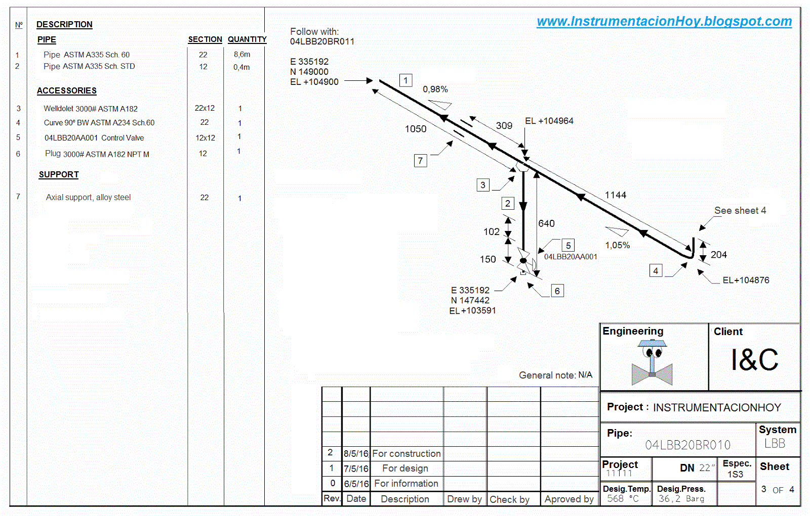
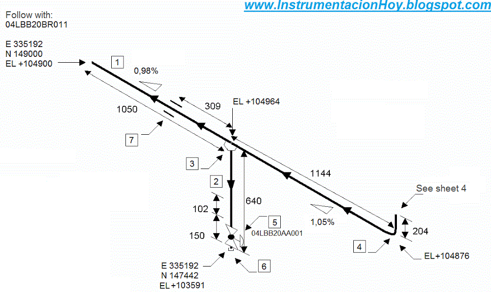
Isometric offset
Table of Contents
Table of Contents
Are you struggling to read isometric drawings? Do you find it overwhelming to make sense of these technical drawings? Fear not, as this post will guide you through the process of comprehending isometric drawings and help you develop the skill needed to read them with ease.
Pain points related to how to read isometric drawings
Isometric drawings can be difficult to decipher, especially for those who lack formal training in engineering or architecture. They can appear complex and overwhelming, leading to frustration and confusion. Often, the angles and positioning of components can be hard to comprehend, making it difficult to visualize the structure. Additionally, there is a vast amount of detail included in isometric drawings, including pipe sizes, flow directions, and valve positions, which can be challenging to understand.
How to read isometric drawings
The first step in reading an isometric drawing is to understand the basic elements of the drawing. Isometric drawings are a type of pictorial representation that displays three dimensions of an object in two dimensions. The drawing involves using equal scale axes to represent the object’s height, width, and depth. The horizontal lines on the drawing represent the width and depth, while the vertical lines show the height. The angles in the drawing should be 120 degrees between each axis, and a 90-degree angle should occur where the horizontal and vertical lines intersect.
Once you have grasped the basics of isometric drawings, you can begin to understand the components in the drawing. Firstly, identify the items in the drawing and their spatial relationships. Secondly, establish the sizes of the pipes, valves, and instruments in the drawing. Pay particular attention to pipe sizes, flow directions, and valve positions. Finally, examine each component’s details to identify any other essential information that may be present, such as insulating material, drain pots, or safety equipment.
Summary of the main points
This post has outlined the basic process involved in reading isometric drawings. Firstly, it is essential to understand the fundamental elements of the drawing, including axes and angles. Secondly, identifying each component in the drawing and their spatial relationships. Finally, examining each component’s details to establish essential information such as pipe sizes, flow directions, and valve positions.
Understanding isometric drawings through personal experience
When I first attempted to read an isometric drawing, it felt incredibly overwhelming. The amount of detail included in the drawing made it challenging to understand the components and their spatial relationships. What helped me was breaking down the drawing into smaller parts, examining each element individually, and then piecing it back together. Understanding the fundamental elements of the drawing and identifying the pipe sizes, flow directions, and valve positions were also vital in comprehending the drawing.
The Importance of Accurate Interpretation of Isometric Drawings
Isometric drawings are an essential component of engineering and architecture. They provide a three-dimensional view of a structure in two dimensions, making it easier for architects and engineers to visualize the final product. Accurately reading these drawings is vital as it can help prevent costly mistakes, reduce project completion times, and ensure safety regulations are met.
Elements of isometric drawings
Isometric drawings feature a vast amount of information, making it essential to grasp the essential elements of the drawing. These include; the title block, pipe orientation, pipe sizes, flow direction, insulation details, valve positions, and control equipment. Focusing on these elements will provide a clearer understanding of the drawing and help identify the components and their spatial relationships.
Accuracy is essential
When reading isometric drawings, accuracy is vital. Misreading a valve position or pipe size could lead to costly errors, resulting in wasted money and time. Additionally, misinterpretation of details could lead to safety concerns and the possibility of environmental damage.
Questions and Answers
Q: What is an isometric drawing?
An isometric drawing is a pictorial representation of a three-dimensional object in two dimensions. It displays the height, width, and depth of an object using equal scale axes, making it easier for architects and engineers to visualize a structure.
Q: What are the essential elements of an isometric drawing?
The critical elements of an isometric drawing include pipe orientation, pipe sizes, flow direction, insulation details, valve positions, control equipment, and the title block.
Q: Why are isometric drawings important?
Isometric drawings are important as they provide an accurate representation of a structure, making it easier for architects and engineers to visualize the final product. Accurate interpretation of these drawings can help prevent costly mistakes and ensure safety regulations are met.
Q: How can I improve my ability to read isometric drawings?
Improving your ability to read isometric drawings involves practicing with various drawings, breaking them down into smaller parts, and focusing on the essential elements of the drawing, such as pipe orientation, pipe sizes, flow direction, insulation details, valve positions, control equipment, and the title block.
Conclusion of how to read isometric drawings
In conclusion, reading isometric drawings can be challenging, but it is an essential skill for architects and engineers. Understanding the fundamental elements of the drawing and identifying each component’s spatial relationships is vital in comprehending the drawing’s structure. Accuracy is crucial in interpreting these drawings to prevent costly mistakes, reduce project completion times, and ensure safety regulations are met. By following the process outlined in this post, you can develop the skill needed to read isometric drawings with ease.
Gallery
Piping-How To Read Pipe Rolling/Offset In Isometric Drawing? - Clipzui.com

Photo Credit by: bing.com / isometric offset
Learn Isometric Drawings (piping Isometric)

Photo Credit by: bing.com / isometric piping drawing pipe drawings draw learn autocad construction degree engineering getdrawings
Instrumentation Today: HOW TO READ AN ISOMETRIC PIPING DRAWING

Photo Credit by: bing.com / isometric drawing piping read pipe value instrumentation
Piping_How To Read Isometric Drawings_Basic - YouTube

Photo Credit by: bing.com / piping isometric drawing symbols pdf drawings read paintingvalley
Instrumentation Today: HOW TO READ AN ISOMETRIC PIPING DRAWING

Photo Credit by: bing.com / isometric drawing piping read pipe gif instrumentation


